|
SERIES 250
TEMPERATURE CONTROLLER CONFIGURATIONS |
||||
| Configuration #1: CONTROL | ||||
 |
Here is one temperature sensor (red wire) and a heater (connected to the green wire). The set point is fixed or is under user control at the PC console. | |||
| Configuration #2: CONTROL & MONITOR | ||||
 |
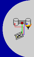
Here are two sensors (red & blue) and a heater (connected to the green wire). The red sensor is the control sensor, however, the temperature at both sensors can be monitored at the PC console. | |||
| Configuration #3: DIFFERENTIAL CONTROL | ||||
 |
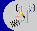
Here are two sensors ( red & blue ) and a pump (connected to the green wire). In this example we control the temperature of vat #1 (left) by circulating hot water from vat #2 (right). The red sensor is the control sensor, however, for DIFFERENTIAL control we allow the blue sensor to adjust the set point. For example, we could tell the controller to keep the set point for vat #1 at 20°C lower than the temperature that is at the blue sensor. Both sensors can be monitored at the PC console. | |||
| Configuration #4: POTENTIOMETER | ||||
 |
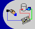
POTENTIOMETER: Here is one sensor (red) and a potentiometer (connected to the blue wire) and a cooler (connected to the green wire). The red sensor is the control sensor. We adjust the setpoint temperature using the potentiometer. | |||