|
|
|
|
Model 5C6-357
(15 Amperes)
Pricebreaks
start at quantity 2
|
Overview


The
Model 5C6-357 is a microprocessor-based
temperature controller specifically designed for laboratory bench-top
applications.
(Replaces the discontinued Models 5C6-353 and 5C6-355, but does not
include
backpanel connection for second sensor.)
The front panel tuning of both proportional
and
integral parameters of the controller allows for use in a wide variety
of applications. The three-digit, seven segment LED display can
indicate
the set temperature or actual temperature in either degrees Celsius or
Fahrenheit.
The set point resolution is displayed in
increments
0.1° below 99.9° and 1° above 100°. This single input
and
single output controller has a standard temperature adjustment range
from
0°C. to 200°C. (32°F. to 392°F.) when used with the
listed
sensor probe series.
This is a
"Zero
Voltage Switching" AC controller. It uses 120 VAC ±20%,
60 Hz line voltage for input and output power. The timebase is 1
second.
Proportional control is achieved by using a portion of a second. 100%
power
means the output power is always on. 50% power means output power is on
for 1/2 second and then off for 1/2 second. 25% power means it is on
for
1/4 second and off for 3/4 second. Your application may require a
different
timebase and we can help you decide whether this or some other
controller
is appropriate for your thermal system.
The tuning parameter for the proportional gain
feature is stated as percent of span. The LED display will indicate 001
to 255 as the adjustment range. This equates to 0.01% of 200 or
0.2°C.
bandwidth to 25.5% of 200 or 51°C. bandwidth. The integral gain
feature
has a similar type LED display scheme. The tuning mode for integral
gain
will indicate a range from 001 to 250. This equates to 0.01 to 2.50
repeats
per minute.
The fully enclosed controller includes a
non-illuminated
power switch, line cord, fuse and fuseholder. A standard three-prong
receptacle
for a heater is an integral part of the controller. Screw down
connectors are provided for the sensor probe input. Input power for the
controller
is 120 VAC with an output load capacity up to 15 amperes.

-
Input Power: 120 VAC ±20%, 60 Hz
-
Heater Power
-
Imax: 15 amperes.
-
Control Mode:Proportional
Bandwidth plus Integral Gain (PI).
-
Control Type: "Zero
Voltage Switching" of the line voltage
(rather
than phase modulated or a voltage based variac).
-
Timebase: 1 Second.
-
Temperature Range: Standard
temperature is
0 to 200C (32°F. to 392°F.). See Sensors
below.
-
Sensing: Single sensor. No temperature
alarms
of cutoffs are built-in. Use an appropriate thermal fuse for safety
power
cutoff.
-
Ambient: For Model 5C6-357 ambient
should
not be higher than 30°C.
Implementation
INITIAL SET-UP AND
OPERATION
The following describes the sequence for initial
set-up of the temperature controller and the re-programming of the
tunable
parameters.
Depress the MENU key prior to applying power
to
the controller. While holding this key down turn the POWER switch to
the
ON position. This operation permits entering the TUNE mode. the LED
display
will indicate "---" and the red TUNE LED will be illuminated.
The °C. or °F. operation is selected
at
this point. The corresponding LED will indicate current status. Either
the UP or DOWN key will toggle between the two selections. Upon
completion
of the selection, advance to the next set-up mode with the MENU key.
SETTING THE "P" GAIN
The ACTUAL TEMP / "P" GAIN LED indicator
should
be illuminated. Use the UP and DOWN keys to scroll through the
proportional
gain range of 001 to 255 per cent of span selection. Remember that 001
is equivalent to 0.1% of the 200° span and is a 0.2°C.
Proportional
Bandwidth. Respectively, a setting of 150 is 15% or a 30°C.
bandwidth
and 255 is 25.5% or a 51°C. bandwidth. Finalize the selection by
depressing
the MENU key again.
NOTES ON THE "P" GAIN
The Proportional Bandwidth is an actual temperature band with the
set
point in the middle of the band. Proportional control only takes place
within the band. So, for example, a 10 degree Proportional Bandwidth
means
that one end of the band is 5 degrees below the set point, while the
other
end of the band is 5 degrees above the set point. If ambient is 25°C
and the set point is 50°C and the Proportional Bandwidth is
10°C,
100% power will be applied until 45°C. At that point proportional
control
begins. As the temperature rises the power applied drops. By the time
you
reach 47.5°C only 50% power is being applied. At 49°C only 20%
power is applied to the load. This proportional drop in power allows
the
set point to be reached in a smooth and controlled manner. It also is
the
main reason for the good end point stability proportional controllers
are
known for.
Knowing that the set point is in the middle of the Proportional
Bandwidth,
and knowing that the "P" Gain value of the 5C6-355 is based on a
percentage
of the 200°C span, here is an easy way to set
the "P" Gain value based on when you want 100% power to end and
proportional
control to kick in:
"001" means PI control begins at "00.1" °C
off the set point.
"010" means PI control begins at "01.0" °C
off the set point.
"050" means PI control begins at "05.0" °C
off the set point.
"150" means PI control begins at "15.0" °C
off the set point.
"255" means PI control begins at "25.5" °C
off the set point.
So, simply dividing the "P Gain value by 10
tells
you how many °C of proportional control you will have near the set
point..
SETTING THE "I" GAIN
The SET TEMP / "I" GAIN LED indicator should
be
illuminated. Use the UP and DOWN keys to scroll through the integral
gain
range of 001 to 250 which selects the repeats per minute of the
integral
action. In this case, the selection of 001 equates to .01 repeats per
minute
and 250 is 2.50 repeats per minute. Finalize this selection by
depressing
the MENU key again.
NOTE ON "I" GAIN
Always start with an "I" Gain of zero when tuning the controller.
Set
your "P" Gain so that the set point is, or is almost reached as a
stable
temperature. If the stable temperature is below the actual set point,
increase
the "I" Gain to compensate for the "droop".
EXIT
To exit the TUNE mode and return to normal
control
using the new settings, turn the POWER switch OFF and then back
ON.
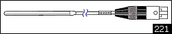
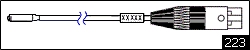
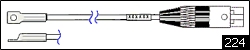
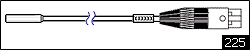
Sensors
Example of an ordering number for a sensor:
TX12-238 (The Temperature Sensor Model followed by the Probe Style).
Let
us know if you need a temperature range that is different from what is
shown below.
Note: Sensor ranges are wider than shown (e.g. 0 to 200
C.) with looser end point tolerance.
Temperature controller range for all sensors:
0°C
to 200°C (32°F. to 392°F.)
Pricing
MODEL 5C6-357 (Can supply 15 Amperes)
Note: Ambient <=30°C
(86°F)
Quantity 01 price:
each
Lower prices are available at higher volume starting at quantity 2.
-
Payment
-
Check, wire transfer, VISA, Mastercard,
Discover,
American Express, Electronic Check, PayPal.
-
General Notes on Pricing
-
Controllers Only: Prices shown are
for the
"controllers
only".
-
Currency: All prices are $US.
TEMPERATURE SENSORS
Ohms@25°C
THERMISTOR SERIES
•
•
•
•
•
•
•
•
•
•
•
RELATED SENSOR PAGES
•
•
•
DESIGN & MANUFACTURING
•
•
With our RS485/RS232 interface you can run any RS485 device off your computer's serial port (the RS232 COM port). Our interface is an opto-isolated "Automatic Transmit-Enable" converter (°3000VDC, 1 second). This device is RS232 to RS485 and back with 9-35VDC single-supply operation, communications status lights, on-board RS485 protection, and other enhancements. Includes enclosure, power supply and RS-232 cable.
Model IHV24AT-B9FSPS
$140.00 QTY1
when purchased with controllers.
$180.00 QTY1 Alone
OEM/QTY pricing is available.
RS232 SERIAL PORT CONNECTION
Usually you connect to the serial port of the computer using
a female DB9 or female DB25 connector. Also referred to as a
female 9 pin, or female 25 pin, D-shell connector. The serial
port is RS232C (or RS-232C). RS232 stands for Recommended
Standard number 232, and the C stands for revision C. Each RS232
device at our site connects to an RS232C serial port through
a cable you provide (unless otherwise noted). 3 wires are generally
used: Signal Ground, Trasmitted Data (TD), and Received Data (RD),
otherwise referred to as Ground, Transmit and Receive. At both
ends of the cable, pin 1 is Ground. At the computer,
Receive is pin 2, while at the peripheral (e.g., temperature controller)
it is pin 3. At the computer,
Transmit is pin 3, while at the peripheral it is pin 2. The connection
is made via "twisted pair" - which
means the Transmit and Receive lines are twisted around each
other along their length, from one end to the other. For the cable, solid copper wire
is preferred over stranded wire simply because there are no strands
at the end that can break off, or bend out, and short the connection. With appropriate
converters you could connect by other means, such as infra-red light (e.g., IrDA).
AMBIENT OPERATING TEMPERATURES
Definition of Ambient Temperature
"The temperature of the atmosphere, liquid, or other medium surrounding an object."
Source: The World Book Dictionary, © 1966 by Doubleday & Company, Inc.
Low Ambient Operating Temperatures
Almost all of our temperature controllers will function at ambient temperatures down to -20ºC (-4ºF).
Many designs will accept a -40ºC (-40ºF) operating ambient. Custom controllers can be built to operate down to -55ºC (-67ºF).
Operation at the low ambient is determined by the ICs used and their ability to have
the correct gain and stable states. The output or load circuit may require
increased drive to turn on. Any design that is specified to a low ambient
operating temperature has been tested and shown to provide sufficient output
drive at that temperature.
High Ambient Operating Temperatures
The high temperature is harder to define than the low, because the high ambient
operating temperature depends upon the controller power dissipation and
the heat sink dissipation.
For all our Pulse Width Modulated (PWM) controllers the following applies:
The power dissipation of the controller is largely a function of the load
current, and only slightly a function of the input voltage. Example: A
unit running at 28v and 25 amps will dissipate the same power into the
base as one which is 12v and 25 amps, however reducing the load current
to 12.5 amps will reduce the power dissipation into the base by 1/2.
For an analog controller, the standard 1/4 power point analysis applies
when determining power dissipation.
Specific Examples
TECC:
The TE controllers are limited by the base plate (mounting bracket) temperature,
because this is the heat sink for the bi-phase H-Bridge. Under full load
the controller will be dissipating approximately 15 watts into the base
plate, Therefore, if the controller is operated at elevated temperatures
you need to provide additional heat sinking for the base plate. At laboratory
temperatures (room temperature, about 20ºC or 70ºF) the controller
will reach about 75ºC under full load. So if you provide an additional
heat sink which results in, say. 70ºC in a 50ºC ambient, the
controller will still function appropriately.
Model 5C6-353: This Laboratory Benchtop Temperature Controller with a 10
Ampere maximum output is designed to run in a laboratory environment. Maximum
ambient operating temperature is 35ºC to 40ºC (95ºF to 104ºF).
Model 5C6-355: This Laboratory Benchtop Temperature Controller with a 15
Ampere maximum output is designed to run in a laboratory environment. Maximum
ambient operating temperature is 30ºC (86ºF).
Model 5CX-140: The 5CX-140 series of controllers have a "derating curve"
(see below) on the customer drawing that is defined by the temperature of the case.
 5CX-140 Series Derating Curve
ZERO VOLTAGE SWITCHING
(or ZERO VOLTAGE FIRING)
Zero Voltage Switching means that the power to the load (heater or cooloer or other device) is switched on
or off only when the output voltage is zero volts.
Zero Voltage Switching can extend the life of a controller and of the load being congtrolled.
Controllers with Zero Voltage Switching use triacs or other solid-state relays instead of mechanical relays,
and, in fact, all of our temperature controllers which use a triac are inherently Zero Voltage Switching.
With AC current, the voltage is zero 50 to 60 times per second. For example, with 120VAC at 60Hz the voltage
swings from 0 volts to -120 volts to 0 volts to +120 volts and back to 0 volts 60 times per second. The controller
only turns the power to the load on or off when the voltage is zero. (Since the cycle described above repeats
itself, there are, at 60 Hz, 120 times every second that the AC voltage is at zero volts and power switching
can occur.
With DC power, as used with thermoelectric controllers, the DC voltage is first converted by the controller
to DC PWM (DC voltage that is Pulse Width Modulated). The voltage repeatedly goes from a positive or negative voltage
to zero volts, and so this type of output power can also be switched on or off when the voltage is zero. The
frequency of these pulses is high enough that the effecton the peltier device approximates that of DC
power (without pulsing), and so pulsing the voltage in this way does not harm the peltier device.
Zero Voltage Switching has an advantage over the kind of switching that would normally be accomplished
with a coil relay beacuse there is a reduced chance for electrical arcing. A relay could turn te power
on when the voltage is high and then an electrical arc (spark) could result.

 Overview


 TOP
TOP